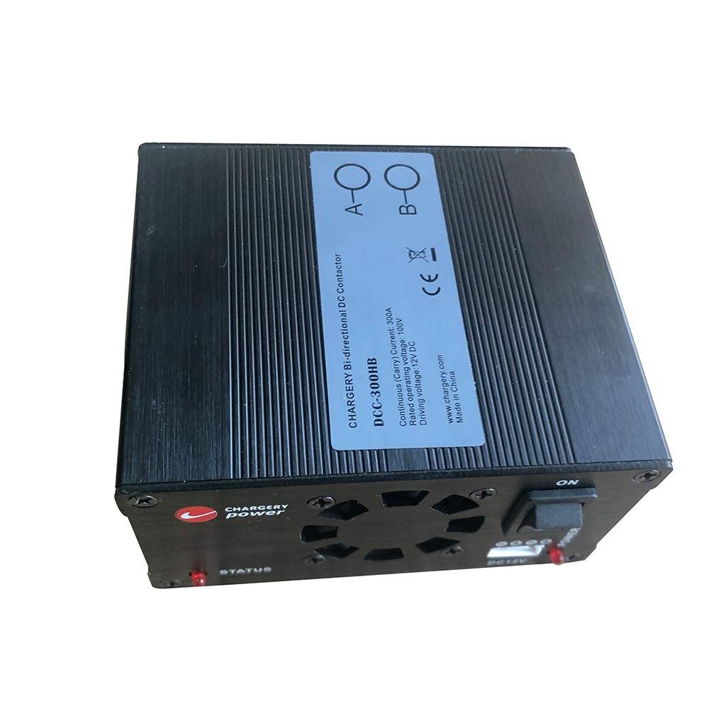
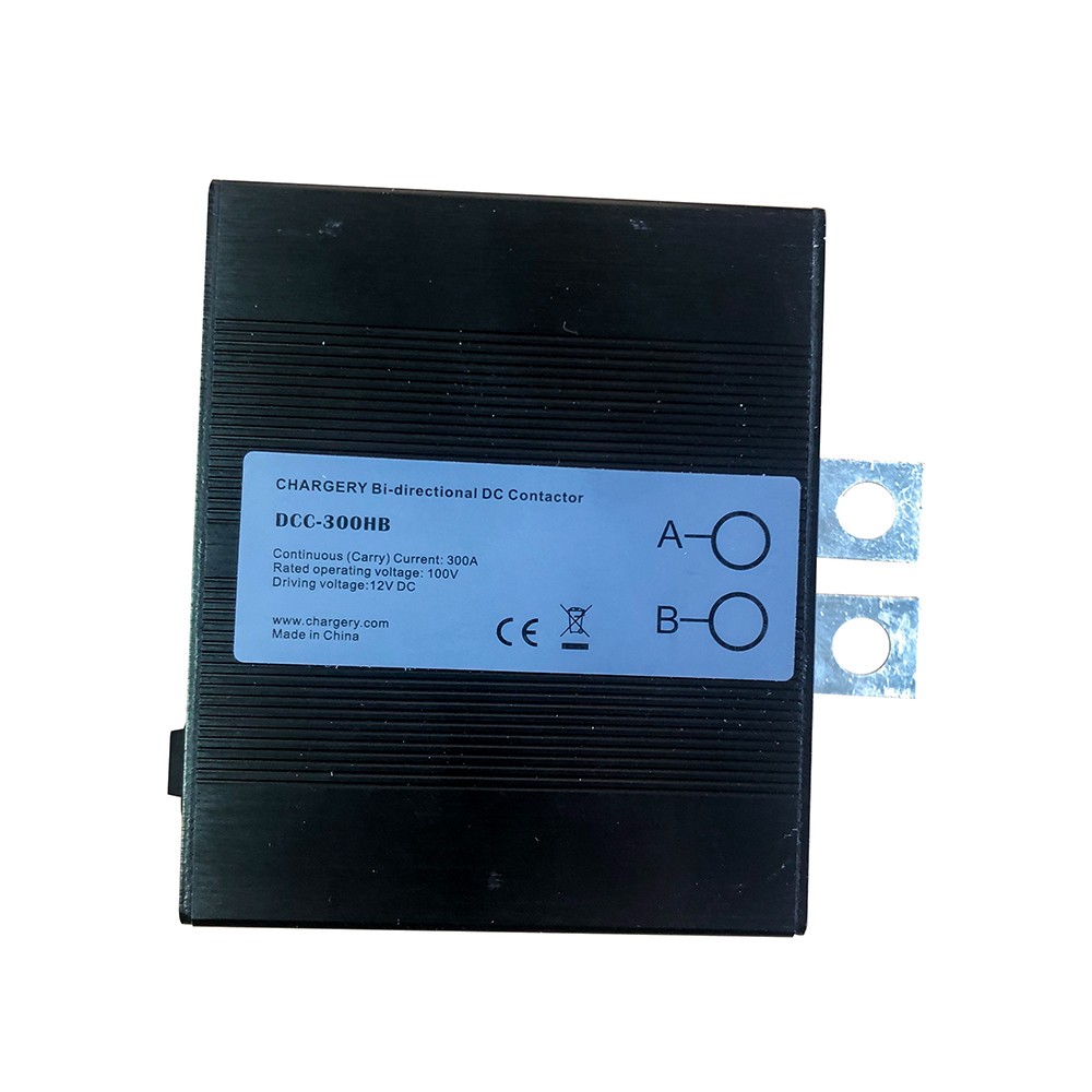
Chargery Power Bi-directional 100V 300A DC Contactor
Bi-directional 100V 300A DC Contactor is designed special work with BMS for Home application such as Energy Storage Systems, Electric drive vehicles
- Category: Other Lithium Battery
- Tag:
Features
The DC contactor is designed special work with CHARGERY BMS’, the following are some features:
1. Bi-directional connection, one DCC can be used in a Common port such as a Solar system, instead of two SSR's (Solid State Relays) or conventional relays.
2. The DCC has a Built-in surge suppressing circuit, thereby eliminating the need for the additional Relay Delay Time board which is used to avoid a surge current when starting to charge or discharge. For other SSR's or mechanical relay, please consider the surge current potentials seriously and make a suitable plan for using a delay board as applicable.
3. Over-temperature protection. If internal temperatures over heat, the contactor will shut off.
4. 1 Intelligent cooling fans turned on automatically
5. Approved by CE
6. 12 months warranty
Application
1. Home application such as Energy Storage Systems.
2. Electric drive vehicles
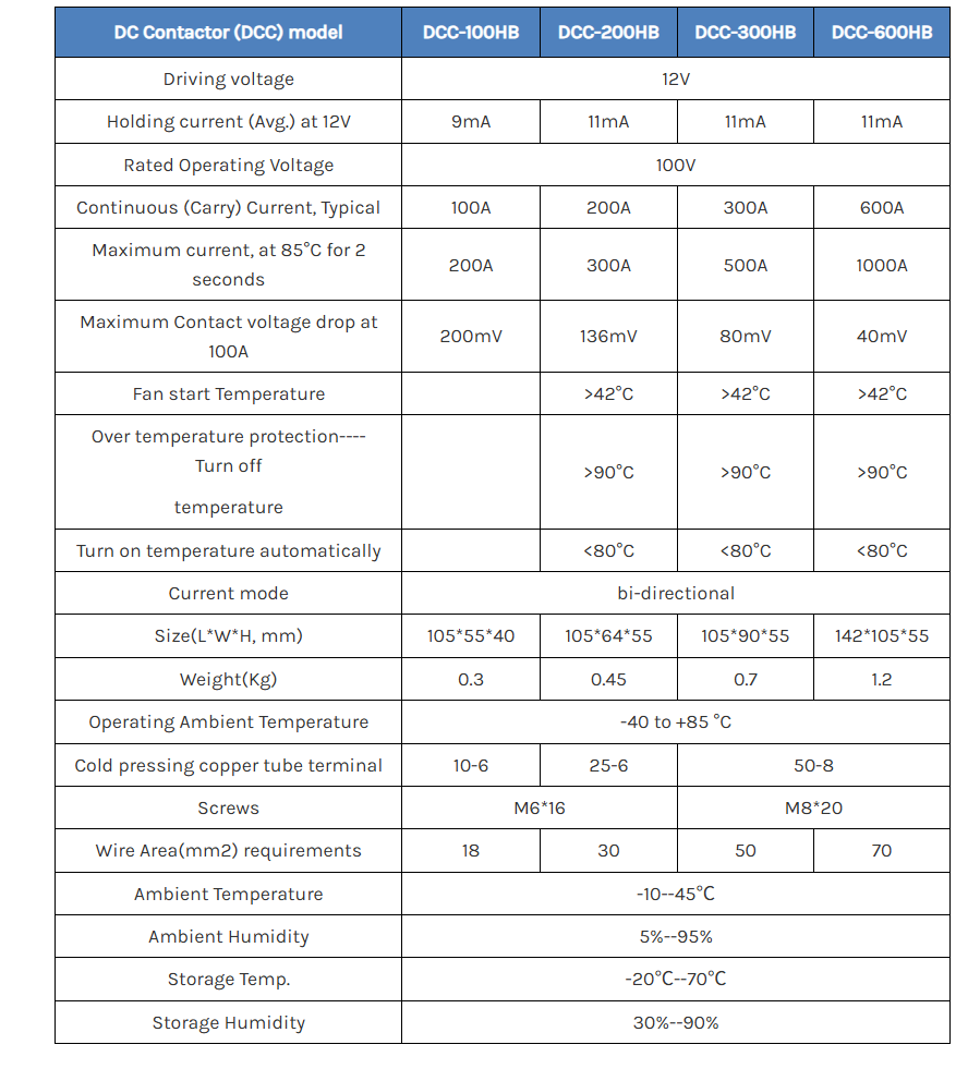
Main Specification
Packaging Information
Chargery DC Contactor (DCC) Operation Instructions
1. Connect all device according to manual. But keep all device turn off, including inverter/charger and DCC.
2. Connect Battery positive to DCC then connect to charger positive/ load positive, if possible install a fuse between DCC and battery positive.
3. Connect charger negative/load negative to shunt (shunt is connected to battery negative), the charger and / or loader/inverter can monitor battery voltage if with these device is with LCD (actual value is lower 0.5V than battery voltage), but cannot charge or discharge because of the pre-charge circuit.
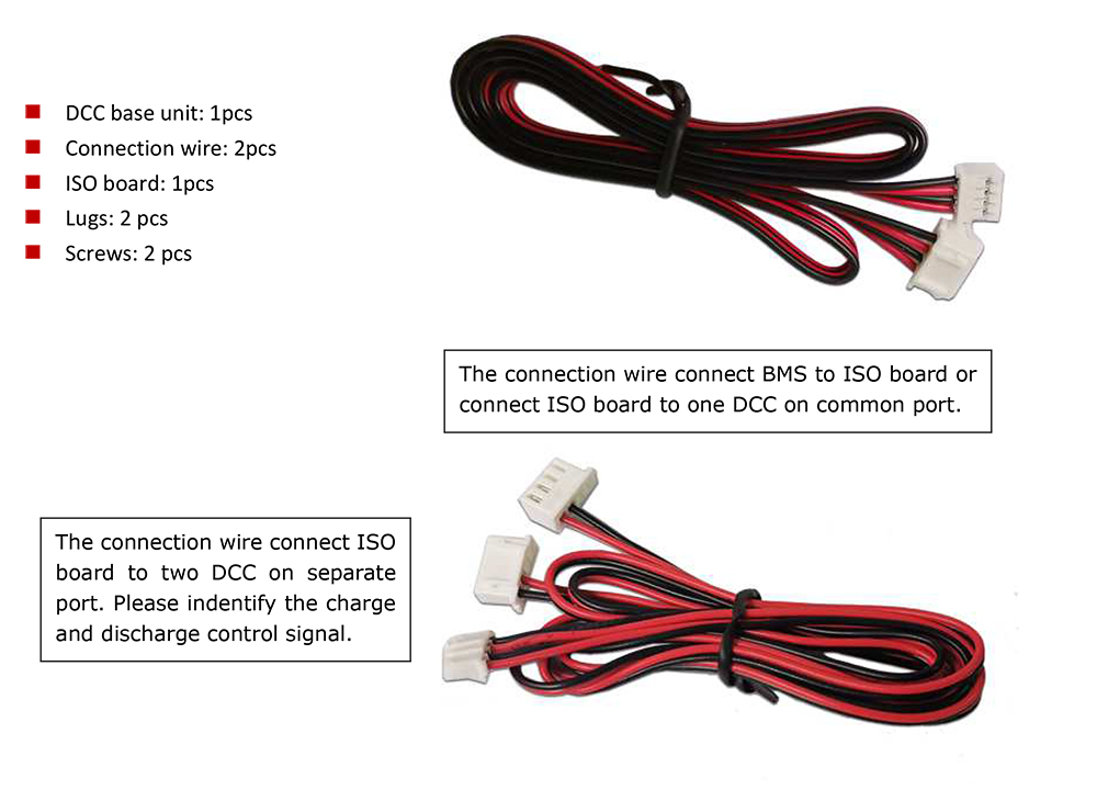
4. Turn off DCC, connect BMS to ISO board, two LEDs (charge LED and discharge LED) will be on if there is not any warnings trigger on BMS, then connect to DCC, two LED is off. No charge current or discharge current flow DCC, even BMS has not any warning.
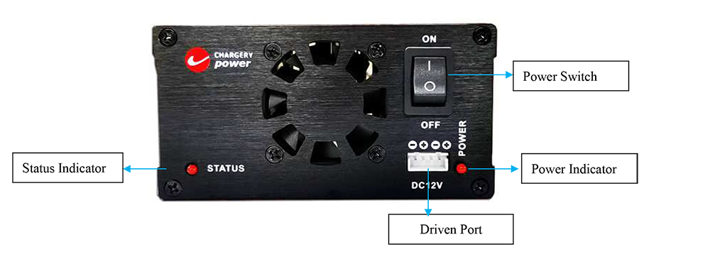
5. Turn on DCC, The power LED and STATUS LED will be on, if there is warning trigger, the Status LED is off. At the same time, one or both LED on ISO board will be OFF, the LEC can indicate charge or discharge is cutting off.
6. Turn on charger, charge current flow DCC, if over charge triggered, the charge LED on ISO board and Status LED on DCC will be off.
7. Or turn on loader/inverter, discharge current flow DCC, if over discharge/cell voltage difference/ soc /temperature etc triggered, the discharge cut off. the discharge LED on ISO board and Status LED on DCC will be off.